Just Because You Can Doesn’t Mean You Should

Build it or Buy It | Endurica - Get Durability RightWhen you have an unmet simulation or testing need, should you build or buy the capability?

There are testing instruments and software packages available in the market – which have been improved through years of R&D and quality management – that can meet the needs of a technical team in their product development efforts. Despite these turn-key resources, we sometimes see a company tasking some of its engineers to build their own.

Why does this happen?

Companies hire smart and creative engineers and scientists with advanced degrees to populate their R&D centers. It is common, and even expected in many situations, for a graduate student to create customized equipment or software as a part of a Ph.D. or M.S. research project. Pushing the boundaries of science and technology often requires such development of devices or code. Also, limited research funding in academia can force students to build their own equipment. When young engineers start their industrial careers after graduate school, they carry with them the mindset of building and programming things themselves. These individuals excitedly offer to create when a new analysis or measurement need arises within a company, and managers like to encourage the enthusiasm of their technical staff.

But, even if your sharp engineer can build a DIY testing device or computer program that recreates the state-of-the-art commercial products created by teams of engineers across many years, is this an efficient and strategic use of the engineer’s abilities? If your company makes tires, for example, then shouldn’t you have your smart people focused on making better tires rather than making testing instruments or software?  What are the labor costs, and the opportunity costs, of your highly-skilled engineer building a piece of testing equipment compared to the price of the commercial instrument or relative to the return you could make on an actual improvement to your product? Unless you are in a position to surpass the commercial solution, there is no competitive advantage in the DIY solution. Once you have created your own solution, who will maintain and support it? Will you be able to keep it up to date with advances in technology? Do you have the capabilities and resources to validate your solution more strongly than the market has already validated the commercial solution?

Unless you are Anakin Skywalker, DIY is not always a winning strategy

Through my 15 years of experience in materials research and development in the tire and rubber industry, I have seen several pieces of home-built testing equipment collecting dust within companies. Either they were half finished and abandoned or could only be reliably operated by the creator who moved to another department or company.

There can be circumstances where the needed instrument or simulation product is not commercially available. Sometimes the capability exists in the marketplace, but it is not discovered because the maker mindset leads to a halfhearted search. For customized solutions, you may consider working with a vendor to leverage their expertise in creating the required device or program.

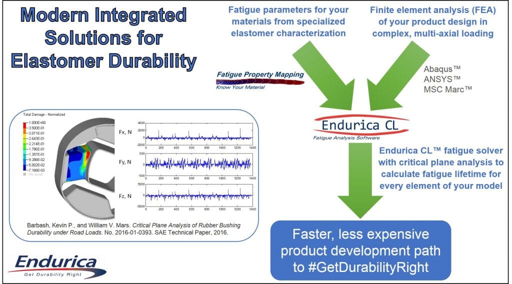
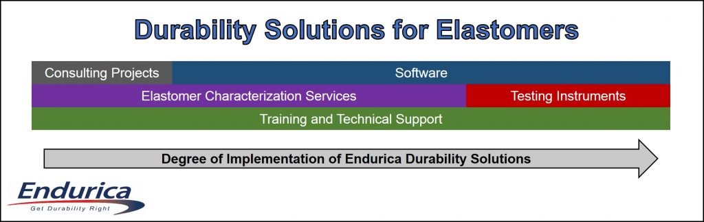
If your analysis and testing needs are in the rubber fatigue and lifetime area, please talk to us before you decide to invest in creating your own solutions. Our solutions embody decades of experience. They are the most competitive and strongly validated solutions you can buy. Endurica has specialized finite element analysis software that predicts elastomer durability for complex geometries and loads, and we offer testing instruments for accurately characterizing the fracture mechanics of elastomers through our partnership with Coesfeld GmbH & Co. KG. We can take you quickly to the forefront of fatigue management capabilities.


twitterlinkedinmail

Integrated Durability Solutions for Elastomers

Will the durability of your new rubber product meet the expectations of your customers? 

Do you have a comprehensive capability that fully integrates all of the disciplines required to efficiently achieve a targeted durability spec?

Your engineers use finite element analysis (FEA) to model the elastomer component in the complex geometry and loading cycle for the desired product application.  One traditional approach to predicting durability is to develop a rough estimate of lifetime by looking at maximum principal strain or stress in relation to strain-life or stress-life fatigue curves obtained for the material using lab specimens in simple tension.  The difficulties and uncertainties with this method were discussed in a recent blog post.

a rough estimate of lifetime by looking at maximum principal strain or stress in relation to strain-life or stress-life fatigue curves obtained for the material using lab specimens in simple tension


A modern approach to elastomer durability is to use the Endurica CL™ durability solver for FEA.  This software uses rubber fracture mechanics principles and critical plane analysis to calculate the fatigue lifetime – which is the number of times the complex deformation cycle can be repeated before failure – for every element of the model.  This provides engineers with the ability to view lifetime throughout the FEA mesh, allowing them to modify design features or make material changes as needed to resolve short-lifetime areas.

view lifetime throughout the FEA mesh, allowing them to modify design features or make material changes as needed to resolve short-lifetime areas.

A sound finite element model of the elastomer product in the specified loading situation and fundamental fatigue material parameters from our Fatigue Property Mapping™ testing methods are the two essential inputs to the Endurica CL software.  This is illustrated in the figure below.

A sound finite element model of the elastomer product in the specified loading situation and fundamental fatigue material parameters from our Fatigue Property Mapping™ testing methods are the two essential inputs to the Endurica CL software.

The requisite elastomer characterization methods can be conducted by us through our testing services or by you in your laboratory with our testing instruments.  For some companies, consulting projects are a route to taking advantage of the software before deciding to license the unique predictive capabilities.  The following diagram shows how our products and services are integrated.

Durability Solutions for Elastomers

For companies that are just getting started with implementing our durability solutions, the following is a typical testing services and consulting project:

  1. We use our Fatigue Property Mapping™ testing methods, through our collaboration with Axel Products Physical Testing Services, to characterize the properties of cured sheets of rubber compounds sent to us by the client. The minimum requirements for fatigue modeling are crack precursor size and crack growth rate law, and these are quantified within our Core Fatigue Module.  Special effects like strain-induced crystallization and aging/degradation are accounted for using other testing modules when applicable.
  2. The client sends us the output files from their finite element analysis (FEA) of their elastomer part design for the deformation of their complex loading cycle. It is common for the goal to be a comparison of either two designs, two distinct loading profiles, two different rubber compounds, or combinations of these variations.  Our software is fully compatible with Abaqus™, ANSYS™, and MSC Marc™, so the simulations can be conducted on any of these FEA platforms.  In some situations where a client does not have their own FEA capabilities, one of Endurica’s engineers will set up the models and perform the analyses instead.
  3. The fatigue parameters and FEA model are inputted to Endurica CL fatigue solver to calculate values of the fatigue lifetime for every element of the model. The lifetime results are then mapped back onto the finite element mesh in Abaqus, ANSYS, or MSC Marc so that the problem areas (short lifetime regions) within the geometry can be highlighted.
  4. We review the results with the client and discuss any opportunities for improving the fatigue performance through design and material changes.

Advanced implementors of our durability solutions have licensed the Endurica CL software and are using our rubber characterization methods in their laboratories on a routine basis, with instruments provided through our partnership with Coesfeld GmbH & Co. (Germany).  One recently publicized example of a company using the Endurica approach to a very high degree is Tenneco Inc., which you can read about here.

We want to help you #GetDurabilityRight, so please contact us at info@endurica.com if you would like to know more about how Endurica’s modern integrated durability solutions for elastomers can help enable a product development path that is faster, less expensive, and more confident.

twitterlinkedinmail

Fatigue Life Analysis of Free Surfaces

Free surfaces are critical in fatigue analysis because cracks in a physical part tend to form and grow fastest on such surfaces.  Extra care is required when analyzing free surfaces because typical 3D solid finite elements have their worst accuracy at the free surface (gauss points are not located on the free surface, and hydrostatic pressure profile does not conform adequately to element shape function).  Fortunately, the problem is not hard to resolve: free surfaces can easily be skinned with membrane elements.  Membrane elements are specially formulated to produce an exact state of plane stress.

Let’s look at fatigue life predictions that have been computed with a skin of membrane elements, and compare them with predictions computed from the underlying 3D solid elements.

To study the differences in fatigue life calculations, three simple loading cases were used: simple tension, planar tension, and bending. For each case the fatigue life is calculated for both the surface and solid elements.  The results are shown in the table below.

The fatigue life results show that the shortest life always occurred on the free surface. The life for the solid elements varied from 16% to 25% longer than the surface elements. In each case, the critical failure location was on the surface of the part and in the same location for both the solid and surface calculations. The colored contours of fatigue life are shown below for each of the cases.

Figure 1. Fatigue life on simple tension specimen. Isometric view.


Figure 2. Fatigue life on planar tension specimen. Cross-section view through the center of the specimen.


Figure 3. Fatigue life on bending specimen. Cross-section view through the center of the specimen.


Mesh refinement affects the fatigue life results. A mesh refinement study was performed on the bending case. The mesh refinement study consists of the standard mesh model shown above, a coarse mesh model and a fine mesh model. The number of elements in each model triples with each increase in mesh density. The results are shown below.

Figure 4. Mesh Density Analysis on bending specimen.

This mesh density analysis shows that as mesh density increases, the difference in the bulk and surface results decreases. The bulk and surface results converge to a single value. The amount that solid elements on the surface of the part extend into the interior of the part decreases as smaller elements are used. Since the smaller solid elements have a strain history closer to the surface they more closely match the surface element strains and the life results converge to a single value.

Bottom Line:  if you have free surfaces, skin your model with membrane elements for high accuracy results.  Refining your mesh at the surface may help somewhat, but skinning with membranes is far more reliable.


twitterlinkedinmail
close
Trial License RequestTrial License RequestTrial License RequestTrial License RequestTrial License Request

Our website uses cookies. By agreeing, you accept the use of cookies in accordance with our cookie policy.  Continued use of our website automatically accepts our terms. Privacy Center