
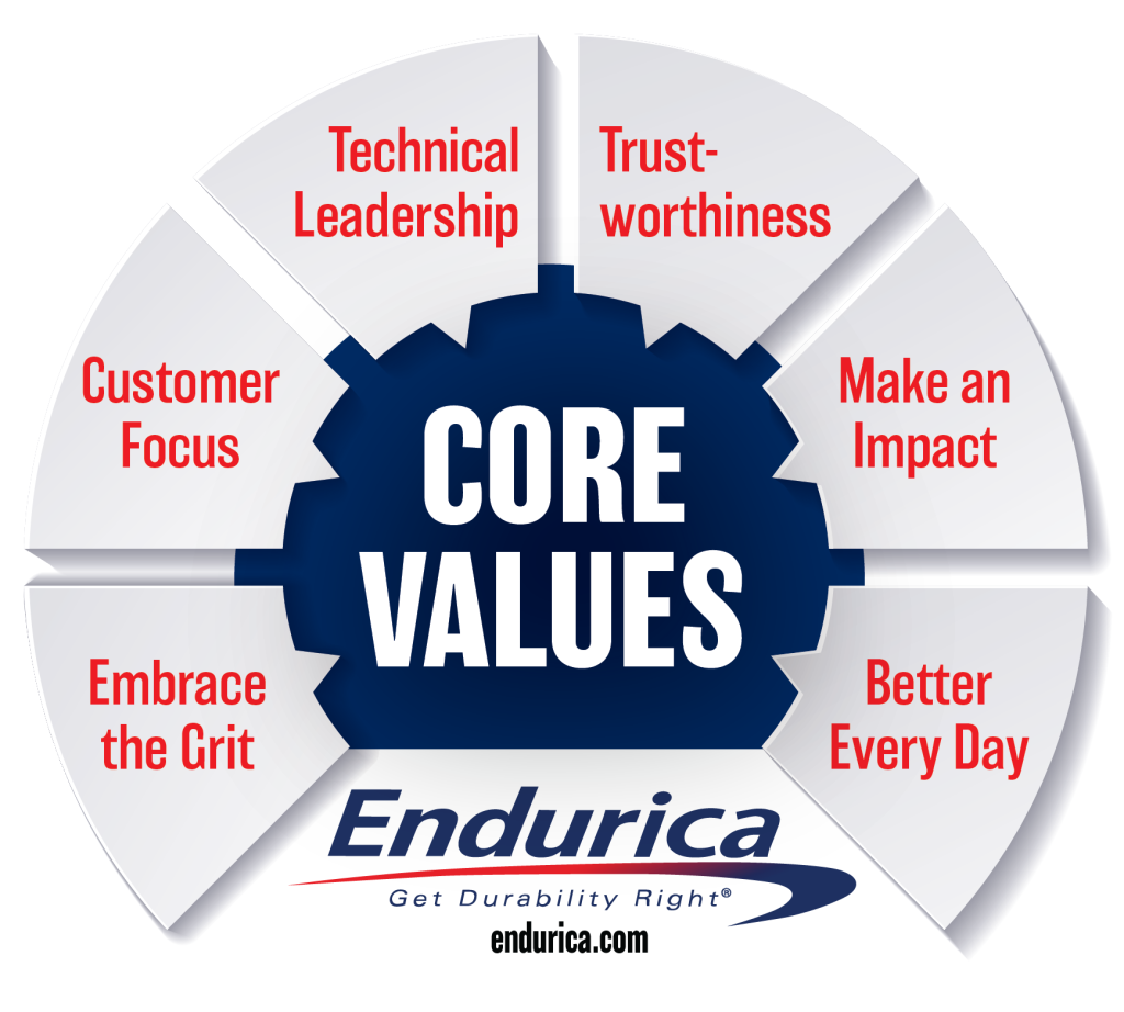
Dr. Will Mars, founder and president of Endurica, challenged attendees to think beyond traditional boundaries and consider the many “Dimensions of Durability” that define product... Continue reading
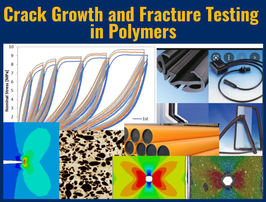
My PhD work at the University of Wisconsin was on crack growth in high density, high molecular weight polyethylene (HDHMWPE) used in natural gas distribution... Continue reading
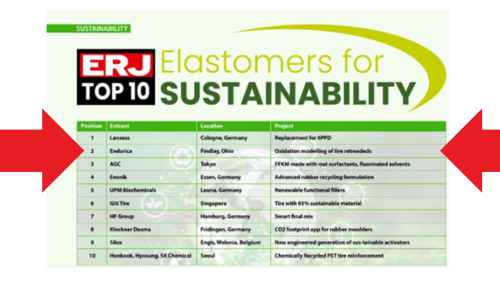
In the September/October 2025 issue of the European Rubber Journal , Endurica was listed as having the second most important project for sustainability! The complete... Continue reading
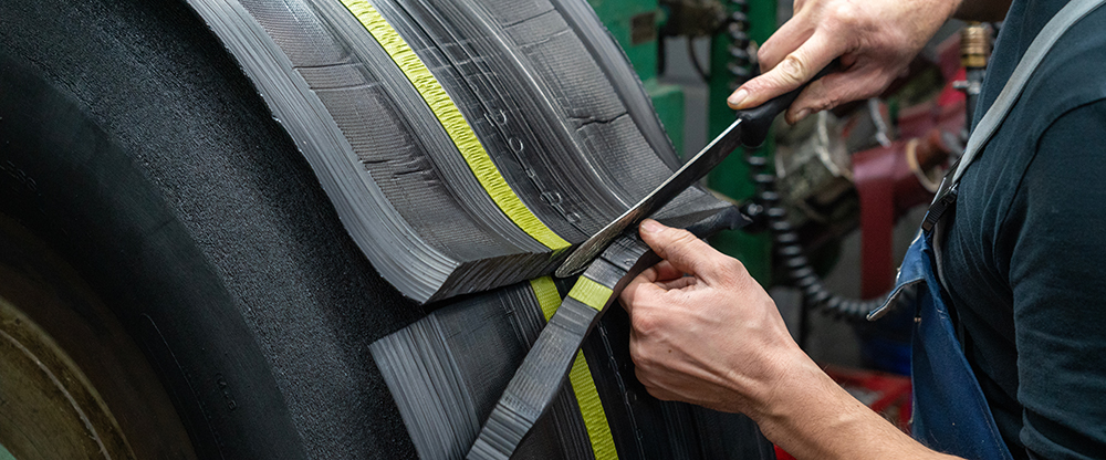
When it comes to building a greener future, the tire industry has a powerful ally: retreading. This time-tested practice extends tire life, reduces waste, and... Continue reading
“I’m pleased to share that my latest article has been accepted for publication” is among the best email subject lines someone in a technical company... Continue reading
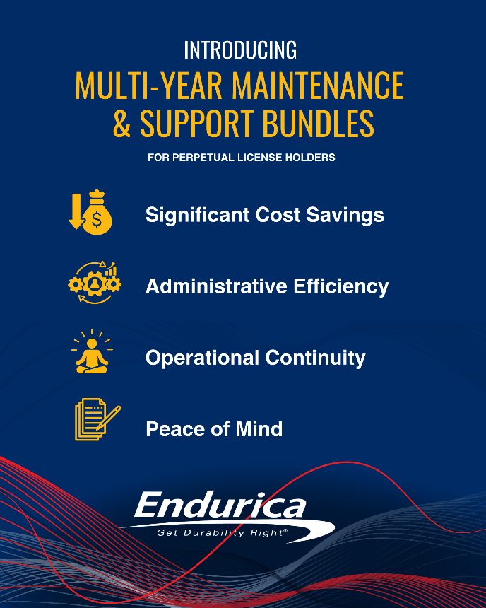
Endurica is committed to building long-term, strategic relationships that support our clients’ success well beyond the initial purchase of a software license. In response to... Continue reading
William V. Mars, Ph.D., P.E. is a co-author of the article A Preliminary Conceptual Study for Coupled Thermo-Mechanical and Structural Characterization of Rim-Supported Run-Flat Tires which... Continue reading
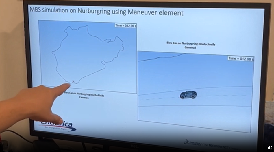
It was May of 2023, and Will Mars had just given a presentation on “Virtual Qualification of the Durability Performance of an Elastomeric Mount with... Continue reading

All materials are temperature dependent, but some more than others: metals tend to be crystalline solids and will melt at sufficiently high temperatures; in contrast,... Continue reading

Wow – this year has really been one of many firsts for Endurica. We had our first ever Community Conference in April, we started our... Continue reading
Showing 1–10 of 56 posts